I wanted to design a robotics project for kids with the following goals in mind:
- Build time not more than about a (longer) afternoon
- Should not be perfect: the kids should feel the need to improve the robot with better hard- and software after the workshop
- No special tools should be required to repair, improve and reprogram the robot
- Should use only cheap components (total about 10 USD - plus the micro:bit controller board for about 20 USD)
- Should be powered by a standard power bank (and not disposable batteries) for environmental reasons
- Should be fun to build and operate
The first two goals (and the 2nd in particular) were rather easy to achieve, so I will not talk about them. But the 3rd turned out to be rather tricky. It excluded soldering, because most parents don’t have a soldering iron at home. I wanted a solution which requires only a simple (small) screwdriver and scissors (which can - for small wire diameters - also replace a side cutter).
I therefore decided to attach 12mm M3 screws to the micro:bit (secure them with an M3 nut from the other side) and screw luster terminals on them. All the cables are - after stripping and twisting - attached to these luster terminals. This proved to be a surprisingly reliable solution.
Most building instructions for soap bubble robots use large diameter fans. But this would make the robot bulky and also rather expensive (which would collide with goal number four above). Therefore in this design only a small (5cm side length) 5V electronics fan is used.
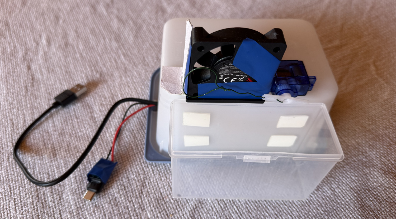
The finished robot looks like this:
(Youtube video of robot in action here)
A small 9g analog servo is moving a small loop made from coated garden wire into a basin (made from a plastic box for playing cards) filled with soap liquid and then in front of the fan. Everything is controlled by the micro:bit. When someone makes a noise (like clapping hands), the fan is switched on first, then the wire loop is plunged into the soap water and then brought in front of the fan.
The electronics are placed into a standard plastic food container „borrowed“ from the parent’s kitchen. This provides some protection from splashing water at least for the more expensive electronic components. The micro:bit is attached to the lid of the container with a 12mm M3 screw / nut. All other components are attached using strong double-sided mounting tape.
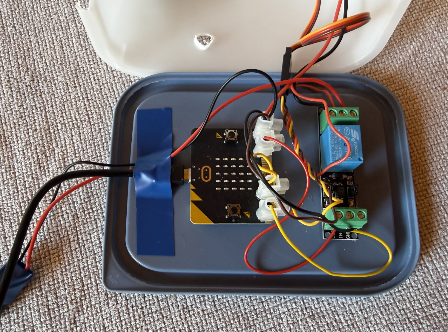
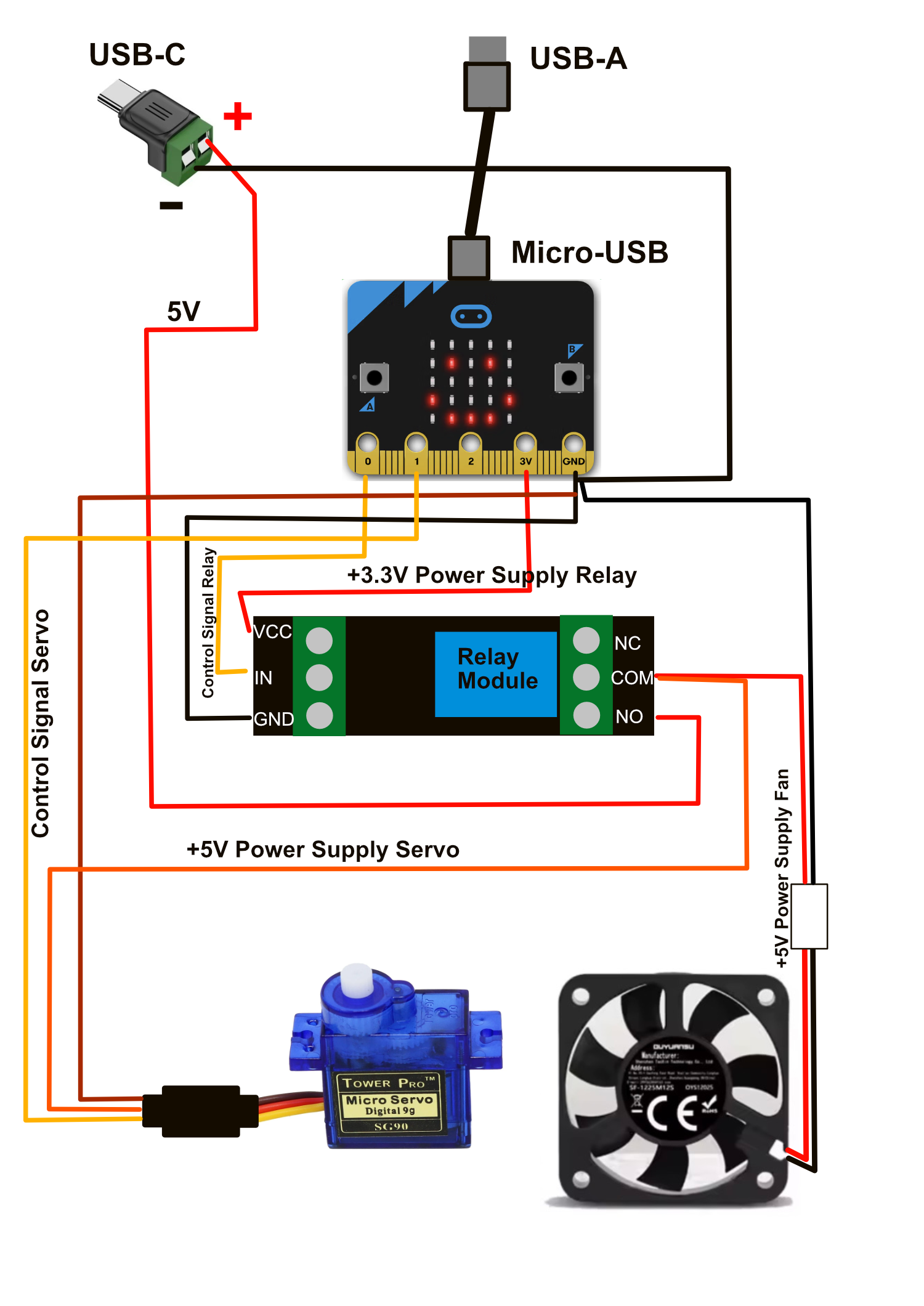
The robot needs both 3.3V and 5V power supplies. The 3.3V generated by the micro:bit (from the micro-USB connector’s 5V) is sufficient to power the 3.3V relay module. But 5V (and also higher current) is required to power both the servo and the fan. The power for the servo and the fan is disconnected by the relay module if they are not in use (to reduce servo jitter and reduce noise / power consumption in standby mode).
The additional 5V are drawn from a small USB-C to luster terminal adapter:
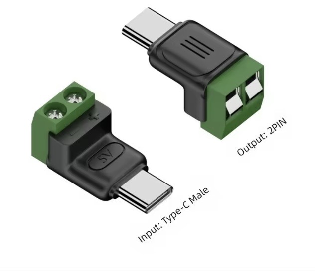
An USB-C cable would work too. Both the adapter and the cable are available in two variants: one to charge the power bank and one to draw power from the power bank. Make sure you buy the latter!
The 3.3V relay module I have used:
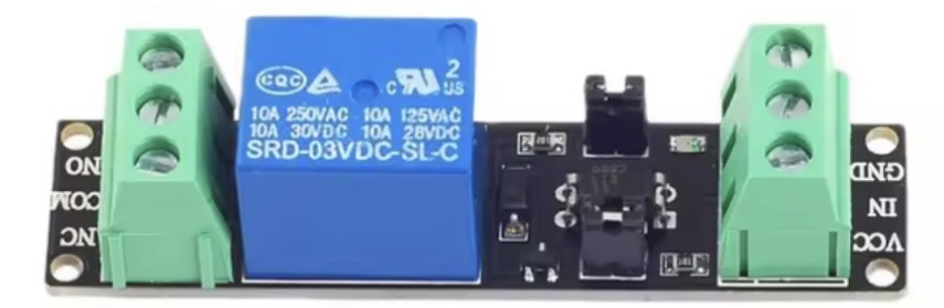
Some notes to the other materials used:
- A servo extension cable (remove the female connector) was used to make it easy to disconnect the servo from the electronics (e.g. in case the servo needs to be replaced)
- Similarly, a JST-XH (2.54mm pitch) 2 pin connector was used to make the fan easy to disconnect. Make sure that the attached cables match in color with the colors of the cables on the fan (I ordered the wrong one and it confused a bit the kids). Depending on the connector already present on your fan, you might need another type of matching connector.
- I used 20 AWG cables in three different colors (black and red for power and yellow for signals. See the schematic)
- A suitable USB-A to micro-USB cable is already included in the standard micro:bit package
- Servo: a cheap SG90 analog 9g servo works fine
- The power bank must have both USB-A and USB-C outputs. On most power banks these can be used simultaneously.
Some tips for a successful build:
- Attach the servo exactly as shown in the first foto (and not like in the video!). This minimizes the length of the wire arm with the loop at the end which helps to reduce vibrations / servo jitter.
- Parts of the fan must be closed with tape as shown in the foto. Otherwise the turbulent air stream around the loop destroys the soap bubbles. The position used in the foto worked best, because the airflow directs the bubbles upwards (instead of downwards, where they again would get destroyed quickly)
- The wire loop must be very close to the fan (about 2-3mm max. distance!). This is not easy to achieve, as the loop must also have enough distance from the wall in the liquid basin to allow the formation of a soap film in the loop. We used a small piece of plastic to create some overhang of the fan over the liquid basin.
- The servo arm does not need to be screwed to the servo. Usually it sticks to the servo firmly enough and having no screw simplifies maintenance a lot.
- If the servo is attached with velcro tape (instead of mouning tape) it's much easier to fine tune the positioning of the servo.
- A good soap bubble liquid is essential for good performance. You will find many recipes on the internet. Experiment.
The software (makecode) for the robot can be downloaded here:
Download Software for micro:bit
from ki-kit.ch
or
from GitHub
You might need to adjust the variables for the various angles of the wire loop before uploading the software to the micro:bit (just guess & experiment with different angles).
Have fun!

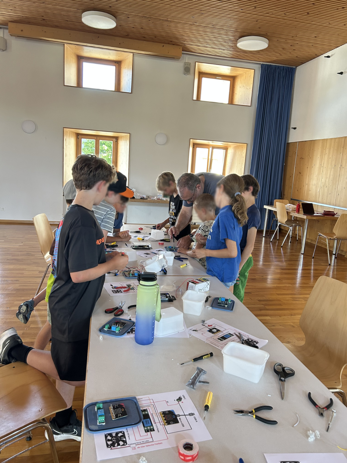
Images: By author (cartoons made with ChatGPT). Component fotos: from dealer website